
Supply Ability :
One million pcs monthOEM/ODM :
SupportCountry of origin :
Anhui, ChinaProduct dimensions :
174x72x207mmProduct weight :
5410gStandard voltage :
3.2VCapacity :
304AhLead time :
A week1.Scope of Application
This file defines the performance requirements, test methods, inspection rules, signs, packing, transportation, storage and safety requirements of rechargeable Lithium-ion battery cell - EC-AU304-NAH3L0, produced by the enterprise.
2.Applicable standards
The clauses in the following documents become clauses of this standard after being quoted in this standard. For undated references, the latest version is applicable to this standard. GB/T 36276-2018 Lithium-ion battery for electrical energy storage
3.Terms & Definition
3.1 Product: Rechargeable Lithium-ion cell EC-AU304-NAH3L0, produced by the enterprise.
3.2 Customer/client: Company or person to buy this product.
3.3 Room temperature: The abbreviation RT, the ambient temperature is 25±2℃.
3.4 Rated charging capacity: At room temperature, the capacity of standard charge to 3.65V after standard discharge.
3.5 Rated discharging capacity: At room temperature, the capacity of standard discharge to 2.5V after standard charge.
3.6 Rated charging energy: At room temperature, the energy of standard charge to 3.65V after standard discharge.
3.7 Rated discharging energy: At room temperature, the energy of standard discharge to 2.5V after standard charge.
3.8 Rate Current: Abbreviated in C, 1C represents the current that the cell charge and discharge at 1 hour; 0.5C represents the current that the cell charge and discharge at 2 hours.
3.9 Rate charging power: Abbreviated in Pc, 1Pc represents the power that the cell charge at 1 hour;0.5Pc represents the power that the cell charge at 2 hours.
3.10 Rate discharging power: Abbreviation in Pd, 1Pd represents the power that the cell discharge at 1 hour, 0.5Pd represents the power that the cell discharge at 2 hours.
3.11 Maximum continuous charging power: The maximum power allowed for continuous charge to ensure the cell normal operation at specified temperature
3.12 Maximum continuous discharging power: The maximum power allowed for continuous discharge to ensure the cell normal operation at specified temperature
3.13 Energy efficiency: Under the specified test conditions and methods, the ratio of the discharge energy to the charge energy of the cell, expressed as a percentage.
3.14 Ambient temperature: The ambient temperature where the cell is located.
3.15 Cell temperature: The temperature of the cell measured by the temperature sensor connected to the battery. The selection of the temperature sensor and the measurement circuit is jointly negotiated by the customer and the enterprise
3.16 State of Charge (SOC): All linear relationships of the state of cell charging capacity measured in ampere-hours or watt-hours under no-load conditions. A state of 100% means that the battery is fully charged to 3.65V, and a state of 0% means that the battery is fully discharged to 2.5V.
4.Basic performance
| NO. | Item | Spec | Remark |
| 4.1 | Appearance | clean surface, no rust, no scratches, no burrs, no deformation and mechanical damage, no electrolyte leakage | N.A |
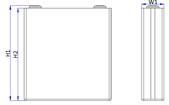
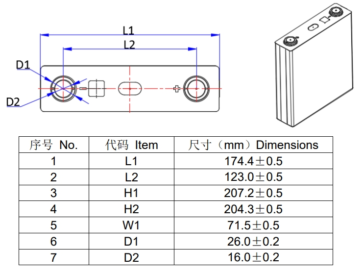
| 4.2 | Dimension |
Thickness:72.0±0.5mm Width:174.0±1.0mm Shoulder height:205.0±0.5mm Total height:207.0±0.5mm |
Thickness test condition: SOC≤30%,pressure of 300±10kgf see appendix for details |
| 4.3 | Weight | 5.41±0.2Kg | N.A. |
| 4.4 | Nominal voltage | 3.2V | RT,0.5Pd/0.5Pc |
| 4.5 | AC internal Resistance | ≤0.5mΩ | RT,1KHz |
| 4.6 | Rated charging capacity | 304Ah | RT,0.5Pd/0.5Pc |
| 4.7 | Rated discharging capacity | 304Ah | RT,0.5Pd/0.5Pc |
| 4.8 | Rated charging energy | 972.8Wh | RT,0.5Pd/0.5Pc |
| 4.9 | Rated discharging energy | 972.8Wh | RT,0.5Pd/0.5Pc |
| 4.10 | Standard charge current | 152A(0.5c) | RT |
| 4.11 | Maximum charging current |
304A(1C) |
≤0℃ not allowed to charge 0℃—60℃ normal ≥60℃ not allowed to charge |
| 4.12 | Cut-off charging voltage | 3.65V | N.A. |
| 4.13 | Maximum charging temp. range | 0℃~60℃ | N.A. |
| 4.14 | Standard discharge current | 152A | RT |
| 4.15 | maximum discharge current | 304A | RT,50% SOC,10s |
| 4.16 | cut-off discharging voltage |
2.5V(T>0℃) 2.0V(T≤0℃) |
|
| 4.17 | Allowable discharging temperature range | -30℃~55℃ | N.A. |
| 4.18 | Storage humidity | ≤75% RH | N.A. |
| 4.19 | Delivery capacity (SOC) | 20%SOC | Adjustable |
5.Electric performance
5.1Initial charging and discharging capacity, initial charging and discharging energy
Table 2 Initial charging and discharging capacity, initial charging and discharging energy
| NO. | Item | Spec | Remark |
| 5.1.1 | Initial charging capacity (0.25Pc) | ≥304Ah | RT,0.25Pc, more on 7.4 |
| 5.1.2 | Initial discharging capacity (0.25Pd) | ≥304Ah | RT,0.25Pc, more on 7.4 |
| 5.1.3 | Initial charging energy (0.25Pc) | ≥972.8Wh | RT,0.25Pc, more on 7.4. |
| 5.1.4 | Initial discharging energy (0.25Pd) | ≥972.8Wh | RT,0.25Pd, more on 7.4 |
| 5.1.5 | Initial charging capacity (0.5Pc) | ≥304Ah | RT,0.5Pc, more on 7.4 |
| 5.1.6 | Initial discharging capacity (0.5Pd) | ≥304Ah | RT,0.5Pd, more on 7.4 |
| 5.1.7 | Initial charging energy (0.5Pc) | ≥972.8Wh | RT,0.5Pc, more on 7.4 |
| 5.1.8 | Initial discharging energy (0.5Pd) | ≥972.8Wh | RT,0.5Pd, more on 7.4 |
5.2Rate charge and discharge performance
Table 3 Rate charge and discharge performance
| NO. | Item | Spec | Remark |
| 5.2.1 | Rate charge energy retention rate |
≥95% ≥90% |
RT,1Pc/0.5Pc, More on 7.5 RT,2Pc/0.5Pc, More on 7.5 |
| 5.2.2 | Rate discharge energy retention rate |
≥95% ≥90% |
RT,1Pd/0. 5Pd, More on 7.5 RT,2Pd/0.5Pd, More on 7.5 |
| 5.2.3 | Rate charge and discharge energy efficiency |
≥85% ≥80% |
RT,1Pd/1Pc, More on 7.5 RT,2Pd/2Pc, More on 7.5 |
5.3High and low temperature charge and discharge performance
Table 4 High and low temperature charge and discharge performance
| NO. | Item | Spec | Remark |
| 5.3.1 | Charging energy retention rate@ high-temp. | ≥98% | 45±2℃,0.5Pc, More on 7.6 |
| 5.3.2 | Discharging energy retention rate@ high-temp. | ≥98% | 45±2℃,0.5Pd, More on 7.6 |
| 5.3.3 | Charging and discharging energy efficiency@ high-temp. | ≥90% | 45±2℃,0.5Pd/0.5Pc, More on 7.6 |
| 5.3.4 | Charging energy retention rate@ low-temp. | ≥80% | 5±2℃,0.5Pc, More on 7.7 |
| 5.3.5 | Discharging energy retention | ≥75% | 5±2℃,0.5Pd, More on 7.7 |
| 5.3.6 | Charging and discharging energy efficiency@ low-temp. | ≥75% | 5±2℃,0.5Pd/0.5Pc, More on 7.7 |
5.4Storage performance
Table 5 Storage performance
| NO. | Item | Spec | Remark |
| 5.4.1 | Discharging energy retention rate@ RT | ≥90% | RT,28D, More on 7.8 |
| 5.4.2 | Charging energy recovery rate@ RT | ≥92% | |
| 5.4.3 | Discharging energy recovery rate@ RT | ≥92% | |
| 5.4.4 | Discharging energy retention rate@ high-temp. | ≥90% | 45±2℃,7D, More on 7.9 |
| 5.4.5 | Charging energy recovery rate@ high-temp. | ≥92% | |
| 5.4.6 | Discharging energy recovery rate@ high-temp. | ≥92% | |
| 5.4.7 | Charging energy recovery rate of storage | ≥90% | 45±2℃,28D, 5.4.8 More on 7.10 |
| 5.4.8 | Discharging energy recovery rate of storage | ≥90% |
5.5 Cycle life
Table 6 Cycle life
| NO. | Item | Spec | Remark |
| 5.5.1 | Cycle life | ≥3000 times | RT,0.5Pc/0.5Pd,80%EOL With fixture, more on 7.11 |
| 5.5.2 | Cycle life | ≥5000 times | RT,0.5Pc/0.5Pd,70%EOL With fixture, more on 7.11 |
6 Safety performance
Table 7 Safety performance
| NO. | Item | Spec | Remark |
| 6.1 | Over discharge | No fire, No explosion | See test method on 7.12 |
| 6.2 | Over charge | No fire, No explosion | See test method on 7.13 |
| 6.3 | Short circuit | No fire, No explosion | See test method on 7.14 |
| 6.4 | Drop | No fire, No explosion | See test method on 7.15 |
| 6.5 | Heating | No fire, No explosion | See test method on 7.16 |
| 6.6 | Crush | No fire, No explosion | See test method on 7.17 |
| 6.7 | Altitude simulation | No fire, No explosion; No electrolyte leakage | See test method on 7.18 |
| 6.8 | Thermal runaway | No fire, No explosion | See test method on 7.19 |
7 Test methods
7.1 Standard test method
The cell being tested should be newly manufactured (less than one-month storage and less than 5 times cycled). Unless otherwise indicated, all test conditions in this specification are as follows: The temperature is 25 ℃ ± 5 ℃, the relative humidity is 15% to 90%, and the atmospheric pressure is 86 kPa to 106 kPa. The room temperature (RT) mentioned in this specification refers to 25 ℃ ± 2 ℃.
7.2 Initial charge
①The cell is stored for 5h at RT;
②The cell is discharged to 2.5V at constant power of 0.5Pd, then rest 30 minutes;
③The cell is charged to 3.65V at constant power of 0.5Pc, then rest 30 minutes.
7.3 Initial discharge
①The cell is stored for 5h at RT;
②The cell is charged to 3.65V at constant power of 0.5Pc, then rest 30 minutes;
③The cell is discharged to 2.5V at constant power of 0.5Pd, then rest 30 minutes.
7.4 Initial charging and discharging capacity, initial charging and discharging energy
At room temperature(0.25Pc /0.25Pd)
① The cell is discharged according to term 7.3;
②The cell is charged to 3.65V at constant power of 0.25Pc, then rest 30 minutes;
③The cell is discharged to 2.5V at constant power of 0.25Pd, then rest 30 minutes;
④Repeat ②~③ 3 times;
Take the average of three charge and discharge capacity and charge-discharge energy as the result.
At room temperature(0.5Pc /0.5Pd)
①The cell is discharged according to term 7.3;
②The cell is charged to 3.65V at constant power of 0.5Pc, then rest 30 minutes;
③The cell is discharged to 2.5V at constant power of 0.5Pd, then rest 30 minutes;
④Repeat ②~③ 3 times;
Take the average of three charge and discharge capacity and charge-discharge energy as the result.
7.5 Rate charge and discharge at RT::
At room temperature, test the charge and discharge rate performance according to following steps:
①The cell is discharged according to 7.3;
②The cell is charged to 3.65V at constant power of 0.5Pc, then rest 30 minutes;
③The cell is discharged to 2.5V at constant power of 0.5Pd, then rest 30 minutes;
④The cell is charged to 3.65V at constant power of 1Pc, then rest 30 minutes;
⑤The cell is charged to 3.65V at constant power of 0.5Pc, then rest 30 minutes;
⑥The cell is discharged to 2.5V at constant power of 1Pd, then rest 30 minutes;
⑦The cell is discharged to 2.5V at constant power of 0.5Pd, then rest 30 minutes;
⑧The cell is charged to 3.65V at constant power of 2Pc, then rest 30 minutes;
⑨The cell is charged to 3.65V at constant power of 0.5Pc, then rest 30 minutes;
⑩The cell is discharged to 2.5V at constant power of 2Pd, then rest 30 minutes;
⑪The cell is discharged to 2.5V at constant power of 0.5Pd, then rest 30 minutes;
⑫The cell is charged to 3.65V at constant power of 1Pc, then rest 30 minutes;
⑬The cell is discharged to 2.5V at constant power of 1Pd, then rest 30 minutes;
⑭The cell is discharged to 2.5V at constant power of 0.5Pd, then rest 30 minutes;
⑮The cell is charged to 3.65V at constant power of 2Pc, then rest 30 minutes;
⑯The cell is discharged to 2.5V at constant power of 2Pd, then rest 30 minutes;
⑰Record the charging energy, discharging energy, charging time, discharging time, charging capacity and discharging capacity of steps ②、③、④、⑥、⑧、⑩、⑫、⑬、⑮、 ⑯;Respectively calculate 1Pc,2Pc 1Pd,2Pd charging and discharging energy retention rate relative to 0.5Pc, 0.5Pd according to the data of steps ②、③、④、⑥、⑧、⑩; Respectively calculate charging and discharging energy efficiency of 0.5Pc and 0.5Pd, 1Pc and 1Pd, 2Pc and 2Pd according to the data of steps⑫、⑬、⑮、⑯.
7.6 High temperature charge and discharge:
①The cell is discharged according to 7.3;
②The cell is stored for 5h at 45℃±2℃;
③The cell is charged to 3.65V at constant power of 0.5Pc at 45℃±2℃, then rest 30min;
④The cell is discharged to 2.5V at a constant power of 0.5Pd at 45℃±2℃;
The ratio of discharging energy to charging energy is the charging and discharging energy efficiency@ high-temp, the ratio of charging energy to initial charging energy (0.5Pc) is the charging energy retention rate@ high temp., the ratio of discharging energy to initial discharging energy (0.5Pd) is discharging energy retention rate@ high-temp.
7.7 Low temperature charge and discharge:
①The cell is discharged according to 7.3;
②The cell is stored for 20h at 5℃±2℃;
③The cell is charged to 3.65V at constant power of 0.5Pc at 5℃±2℃, then rest 30min;
④The cell is discharged to 2.5V at constant power of 0.5Pd at 5℃±2℃;
The ratio of discharging energy to charging energy is the charging and discharging energy efficiency@ low-temp, the ratio of charging energy to initial charging energy (0.5Pc) is the charging energy retention rate@ low-temp., the ratio of discharging energy to initial discharging energy (0.5Pd) is discharging energy retention rate@ low-temp
7.8 energy retention, energy recovery at room temperature
①The cell is charged according to 7.2;
②The cell is stored for 28 days at RT;
③The cell is discharged to 2.5V at constant power of 0.5Pd at RT, then rest 30min; The ratio of the discharging energy to the initial discharging energy (0.5Pd) is the discharging energy retention rate@ RT;
④The cell is charged to 3.65V at constant power of 0.5Pc, then discharged to 2.5V at constant power of 0.5Pd; record the charging recovery energy and discharging recovery energy, the ratio of the charging recovery energy to the initial discharging energy (0.5Pd) is the charging energy recovery rate@ RT, and the ratio of the discharging recovery energy to the initial discharging energy (0.5Pd) is the discharging energy recovery rate@ RT.
7.9 energy retention, energy recovery at high temperature
①The cell is charged according to 7.2;
②The cell is stored for 7 days at 45℃±2℃;
③The cell is stored for 5h at RT, then discharged to 2.5V at constant power of 230W (0.5Pd), then rest 30min; The ratio of the discharging energy to the initial discharge energy (0.5Pd) is the discharging energy retention rate@ high-temp.;
④The cell is charged to 3.65V at constant power of 0.5Pc,then discharged to 2.5V at constant power of 0.5Pd; record the charging recovery energy and discharging recovery energy, the ratio of the charging recovery energy to the initial charging energy (0.5Pd) is the charging energy recovery rate@ high-temp, and the ratio of the discharging recovery energy to the initial discharging energy (0.5Pd) is the discharging energy recovery rate@ high-temp.
7.10 Stored energy recovery rate
①The cell is charged according to 7.2;
②The cell is discharged to 50% of initial discharging energy at constant power of 0.5Pd at RT, then stored for 28 days at 45℃±2℃;
③The cell is stored for 5h at RT, then discharged to 2.5V at constant power of 0.5Pd, rest 30min;
④The cell is charged to 3.65V at constant power of 0.5Pc at RT, then rest 30 minutes, record the charging recovery energy;
⑤The cell is discharged to 2.5V at constant power of 0.5Pd at RT, record the discharging recovery energy; The ratio of the charging recovery energy to the initial charging energy (0.5Pc) is the charging energy recovery rate of storage, and the ratio of the discharging recovery energy to the initial discharging energy (0.5Pd) is the discharging energy recovery rate of storage.
7.11 Cycle life
Take the cell on a fixture of the size more than the cell (for example: 250mm length and 185mm height), keep the cell under pressure of 300±20kgf@50%SOC, then test the cycle life according to following steps at RT:
① The cell is discharged according to 7.3;
②The cell is charged to 3.65V at constant power of 0.5Pc, then rest 30min;
③ The cell is discharged to 2.5V at constant power of 0.5Pd, then rest 30min;
④Repeat②~③, until the end condition, record the cycle times.
7.12 Over discharge
① The cell is charged according to 7.2;
② Discharge at 1C current for 90 minutes or the voltage reached 0V at RT, observe for 1 hour.
7.13 Over charge
①Discharge the battery according to 7.2;
②Take the cell on a fixture of the size more than the cell (for example: 250mm length and 185mm height), keep the cell under pressure of 300±20kgf ;
③Charge at 1C current to 1.5 times the cut-off voltage or the charging time reached 1h, observe for 1h.
7.14 Short circuit
①The cell is charged according to 7.2;
②Short circuit externally for 10 minutes with line resistance <5mΩ, observe for 1 hour
7.15 Drop
①The cell is charged according to 7.2;
②Dropped from a height of 1.5m upside down to a concrete surface, observe for 1 hour.
7.16 Heating
①The cell is charged according to 7.2;
②The cell is placed into oven, and the temperature to of the oven is raised at a rate of 5°C/min to a temperature of 130±2°C and remain for 30 minutes at the temperature before the test is discontinued, observe for 1 hour.
7.17 Crush
Test the crush according to following steps:
① The cell is charged according to 7.2;
② Test according to following conditions:
— Crushing direction: The force for the crushing shall be applied in direction nearly perpendicular to a layered face of positive and negative electrodes inside cell (refer to Figure 1); — Crushing tool shape : A semicylinder with a 75mm diameter, and the length more than the cell — Crushing speed: (5±1) mm/s;
— Crushing degree: voltage of the cell to 0V, or a deformation of 30 % or more of initial cell dimension occurs, or the pressure has reached(13±0.78)kN, remain for 10 minutes before the test is discontinued.
③ Observe for 1 hour.
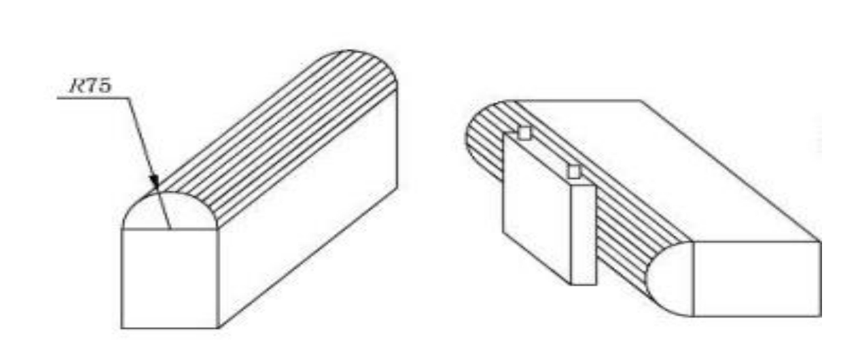
Figure 1 Schematic diagram of extrusion plate and extrusion
7.18 Altitude simulation
① The cell is charged according to 7.2;
② Placed in an altitude simulation test chamber, the pressure is reduced to 11.6 kPa and maintaining this pressure for 6h @RT, and observe for 1h.
7.19 Thermal runaway
①Use flat heating device of the surface should be covered with ceramic, metal or insulating layer, and the heating power is 600~800W. The cell and the heating device fit together, and the heating device and the cell should be in direct contact, and the size of the heating device should not be larger than the heated surface of the cell; Then fit a temperature monitor onto the side away from heat side (the opposite side of the heating device )(see Figure 2), record the temperature data interval of the time less than 1s, The tolerance and the diameter of the temperature monitor should be less than ±2℃and 1mm;
②After the cell is charged according to 7.2, continue charged for 12 minutes at 1C constant current;
③Start the heating device and continue heating the cell with it’s maximum power. When thermal runaway is occurred or the temperature of the monitoring point reached 300°C, turn off the heating device;
④ Record the test results. Whether thermal runaway occurs shall be determined according to the following conditions:
a) The test object occur voltage drop;
b) The temperature at the monitoring point reaches the protection temperature of the cell;
c) Temperature rise rate at the monitoring point ≥1℃/s;
d) When a) +c) or b) +c) occurs, determine that the cell has thermal runaway;
e) During the heating process and within 1h after the heating, if the cell fire or explosion, the test shall be terminated and be judged the cell has thermal runaway.
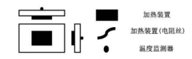
Figure 2 Schematic diagram of thermal runaway test heating
Combining the above standard content and the actual application scenarios of the cell, a supplementary explanation of the test method is provided, as follows:
1) Test tooling: In order to be closer to the actual working conditions, it is required to have a fixture and the cell core to be tested in an upright state. The size of the fixture is not less than the cell;
2) Heating device protection: In order to prevent the insulating film of the cell from being melted during the thermal runaway test, the heating device and the cell can’t be separated after the test, a layer of epoxy board should be placed between the cell and the heating device.
8 Test regulations
8.1The inspection items shall be as specified in Table 8
Table 8. Inspection Items
| Inspection Type | Inspection Items | Inspection Times |
| Initial paramete |
4.4 Nominal voltage 4.6 Rated charging capacity 4.7 Rated discharging capacity 4.8 Rated charging energy 4.9 Rated discharging energy 4.10 Standard charging power 4.11 Maximum continuous charging power 4.12 Cut-off charging voltage 4.13 Maximum charging temp. range 4.14 Optimal charging temperature range 4.15 Standard discharging power 4.16 Maximum continuous discharging power 4.17 Maximum pulse discharging power 4.18 Cut-off discharge voltage 4.19 Allowable discharge temperature range 4.20 Optimal discharge temperature range 4.21 Optimal storage temperature range 4.22 Optimal storage state of charge 4.23 Storage humidity |
/ |
| Pre - delivery inspection |
4.1 appearance 4.2 dimension 4.5 internal resistance |
100% |
| 4.3 Weight | Spot Check | |
| Type Test |
5.1.1 Initial charging capacity 5.1.2 Initial discharging capacity 5.1.3 Initial charging energy 5.1.4 Initial discharging energy 5.2.1 Rate charge energy retention rate 5.2.2 Rate discharge energy retention rate 5.2.3 Rate charge and discharge energy efficiency 5.3.1 Charging energy retention rate@ high-temp. 5.3.2 Discharging energy retention rate@ high-temp. 5.3.3 Charging and discharging energy efficiency@ high-temp. 5.3.4 Charging energy retention rate@ low-temp. 5.3.5 Discharging energy retention rate@ low-temp 5.3.6 Charging and discharging energy efficiency@ low-temp 5.4.1 Discharging energy retention rate@ RT 5.4.2 Charging energy recovery rate@ RT 5.4.3 Discharging energy recovery rate@ RT 5.4.4 Discharging energy retention rate@ high-temp. 5.4.5 Charging energy recovery rate@ high-temp. 5.4.6 Discharging energy recovery rate@ high-temp. 5.4.7 Charging energy recovery rate of storage 5.4.8 Discharging energy recovery rate of storage 5.5.1 Cycle life 6.1 Over discharge 6.2 Over charge 6.3 Short circuit 6.4 Drop 6.5 Heating 6.6 Crush 6.7 Altitude simulation 6.8 Thermal runaway |
GBT 36276- 2018 |
8.2Ex-factory inspection
8.2.1Adopt the GB/T 2829.1-2012 normal inspection one-time sampling plan. The inspection items, required chapter numbers and test chapter numbers are shown in Table 10. The inspection level (IL) is Ⅱ and the acceptance quality limit (AQL) is 2.5.
8.2.2In the pre-delivery inspection, if there is one or more unqualified items, the product should be returned to the production department for reproduction and general inspection, and then submitted for acceptance again. If there’s still one or more failures in the re-inspection, the product should be judged as unqualified.
8.3 Type Test
8.3.1 The product undergoes type testing in one of the following situations
a) New product production and old product conversion
b)/Factory transfer
c)Reproduction after suspension for more than one year
d) Significant changes in structure, process or materials
e) Type test one time per 12 months
Any item failed the type testing, the cell should be regarded as unqualified.
9 Label, Packing, Transportation, storage
9.1 Labeling
Each product should have a clear QR code on it.
9.2 Packing
The product has outer packaging to ensure that the product is not mechanically damaged during transportation, loading, unloading and stacking.
9.3 Transportation
During transportation, violent loading and unloading should be strictly prohibited, to prevent server vibration, impact or squeeze, and to prevent from the sun and rain.
9.4 Storage
The product should be stored in a clean, dry and ventilated warehouse with an ambient temperature of -30℃~60℃ and a relative humidity of ≤75%. The warehouse should not contain corrosive gases; the product should be away from fire and heat sources (not less than 2m.)
It is recommended that the cell be stored at 30% to 50% SOC. When the cell is not used for a long time, charge and discharge it every three months, and charge to 30%~50% SOC to avoid over discharge and affect its performance.
10 safety & warning
10.1Before using, you should read the specifications in detail.
10.2Do not immerse the cell into water or other conductive liquids.
10.3It is forbidden to put the cell into fire or expose it to the environment beyond its working temperature range for a long time. If the working temperature of the cell exceeds 60℃, stop its operation!
10.4Connect the positive and negative poles of the cell strictly in accordance with the signs and instructions. No reverse charging!
10.5 When the electrolyte leaks, avoid contacting the electrolyte to skin and eyes. In case of contacting, wash with plenty of water and seek medical advice. It is forbidden for any person or animal to swallow any part of the cell or the substance contained in the cell.
10.6Protect the cell from mechanical vibration, collision and pressure impact, otherwise the cell might be short-circuited, causing high temperature or fire.
10.7Strictly forbidden to subject the cell to excessive mechanical shock.
10.8 Squeeze, drop, short circuit, leakage and other abnormal problems is strictly forbidden during cell operation.
10.9During use, it is strictly forbidden to contact the cover of cells directly or connect them together via conductors to form a circuit.
10.10 Cells should be stored and used in a place away from static electricity
10.11 During operation, charge, discharge or storage, if the cell suddenly heats-up, emits odor, discolors, deforms or has other reactions, it should be stopped immediately and treated accordingly.
11 End of life management
In order to ensure the security during using cells, the clients should establish an effective tracking system to monitor and record the voltage and internal resistance of each cell. The measurement and calculation methods should be discussed and commonly agreed by the clients and Our enterprise When the capacity of the cell decays to 80% of the initial capacity, the use of the cell should be stopped. Otherwise, Our enterprise will not bear the product quality assurance responsibility based on the product sales agreement and this specification.
Appendix


 IPv6 network supported